BLOG
Reduce Time-to-Market with AI for Industrial Design
MistyWest is always exploring how we can help our clients get to market faster, and the proliferation of AI 3D rendering tools like Midjourney, Vizcom, and KREA are revolutionizing the design process. Industrial designers are now capable of generating concepts, visualizing ideas, and streamlining workflows with remarkable speed and accuracy. In this blog post, I’ll share how MistyWest cuts the time from initial sketching to photo-realistic renders in half by leveraging the AI 3D rendering tool Vizcom in our already fast process.
In March 2023, MistyWest started designing a handheld LIDAR-based 3D scanning device, which commercially launched in early 2024. The project began before the use of AI 3D rendering tools like Vizcom became widely acceptable, but today, let’s use the scanning device as a case study and see how Vizcom bridges the gap between 2D sketches and 3D models when it comes to the iterative design process.
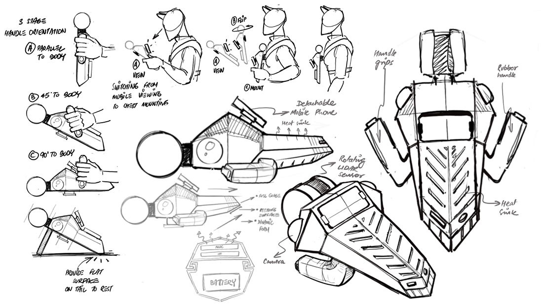
Figure 1: Concept sketches
The Process
1. Prepping and uploading the sketch in Vizcom
To begin, a typical handheld LIDAR-based 3D scanning device has a rotating cylindrical sensor that scans difficult to access and potentially hazardous environments (such as mines and construction sites) to generate 3D maps that are viewable on a display screen.
During the ideation phase of this project, MistyWest generated several new design concepts for our client. For this tutorial, we are focusing on a concept that includes features such as:
-
Double grip that allows users to hold the device with both hands
-
A detachable screen – a mobile phone that could be attached on the device top surface for the user to see the 3D point cloud visuals and other device vitals like battery, scanning and storage levels
-
Foldable legs to provide ground clearance for a rotating sensor, and a chamfered tail to stabilize the device when kept on a flat surface/ground during device initialization
-
A product form that follows an edgy and linear design language
Once a concept like the above mentioned gets shortlisted, the next step is to produce a refined version in the form of a 3D render to be showcased to stakeholders. Before the advent of AI tools, this step used to be a time consuming process involving modeling the concept in 3D, exporting the model, and then visualizing it in a separate rendering software.
However, Vizcom has changed all of this.
First, we pick the relevant sketches (Figure 2) and clean them up by removing unwanted elements like the extra lines, arrows/annotations etc for Vizcom to only pick the right strokes for the 3D visualization.
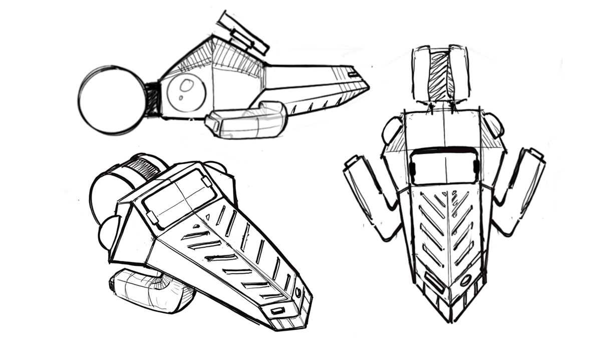
Figure 2: Sketches of orthographic and perspective views
Once the concept sketch is imported (Figure 3), the default interface will show the layers on the left, imported image in the middle and ‘Create’ section on the right.
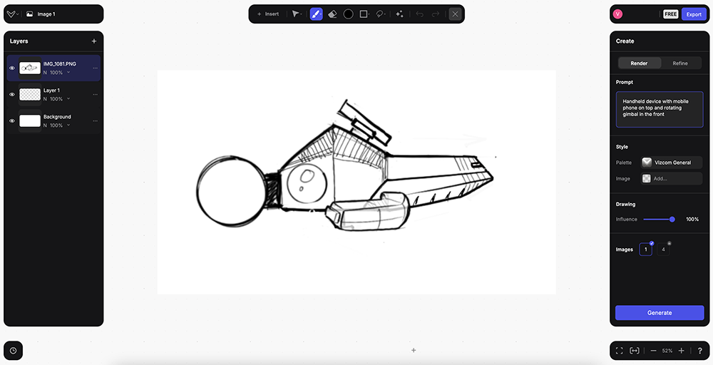
Figure 3: orthographic profile view imported into Vizcom
2. Using Prompts and other features in Vizcom
The ‘Create’ section includes two major subsections – Render and Refine. It also includes the features like ‘Prompt’ for the designer to input text, ‘Styles’ with a drop down list with different rendering options to choose from, and ‘Drawing’ with the sliding ‘influence’ bar to choose the extent to which the render will be influenced by the imported sketch.
By entering the simple prompt ‘handheld device with mobile phone on top and rotating gimbal in the front’ and hitting the Generate button in the render section, we are presented the first version of the render.
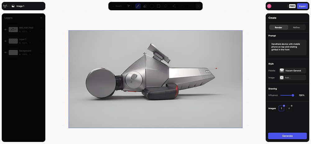
Figure 4: the first render from Vizcom
It’s amazing to see how Vizcom picks up the sketch lines and generates the volume to create the overall product form – all within seconds. Moreover, even with a loose prompt like the one used above, Vizcom was also able to pick the handle grip and choose the right material!
However, such a render has a long way to go before it could be shared with our stakeholders. One of MistyWest’s preferred methods is to enhance the form before delving into correcting the Color, Finish and Material (CFM).
3. Achieving the desired product form
There are two factors that affect the form/render generation.
-
Prompt
-
Drawing Influence
The key is to understand how these two parameters work and affect the form/render.
Keeping Drawing Influence to 100% means that Vizcom is going to be completely influenced by the visual in the viewport while using the prompt/text to only a limited extent. Lowering the Drawing Influence percentage will allow the app to have a higher influence of the prompt on the render.
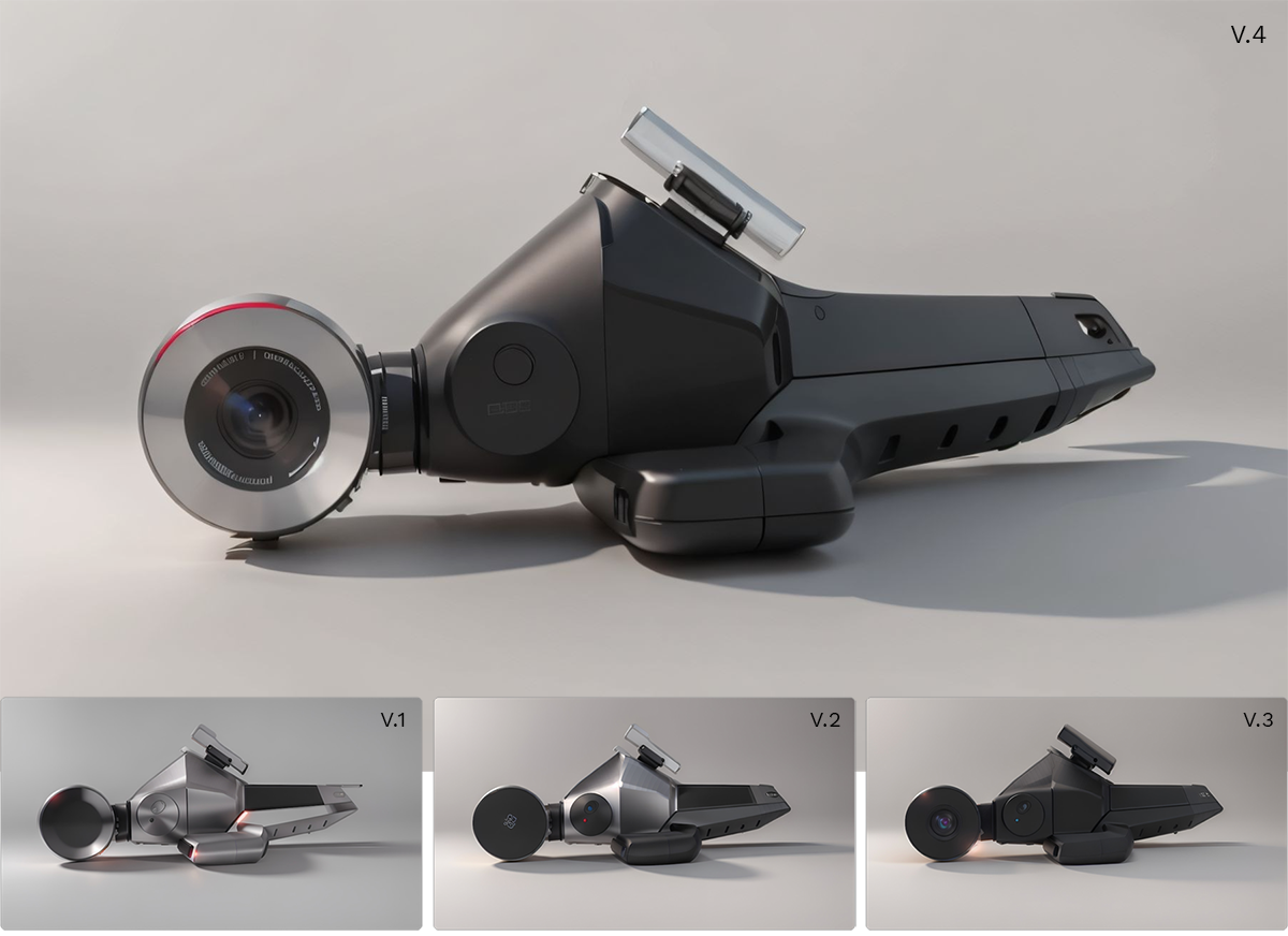
Figure 5: regenerating several times to get a desired result
After keeping the Drawing Influence at 70% and regenerating the form a few times, an acceptable form (Figure 5) is achievable. Figure 5 shows an acceptable version for form development, so here is where we should pause and address the CFM next.
Hot Tip: save the interim renders

As a best practice, designers should save their interim renders by using the Download button as each iteration might have some interesting elements to keep in the final render.
4. Following up with the product CFM
You might notice that through different iterations, the product material has changed from aluminum finish to a complete matte-black. One could use the area selection tool (lasso or brush) and then use either the ‘refine’ or ‘prompt’ features to achieve the desired materials; however, this could be a tedious process. For the selected product concept, rendering the complete product form in a different material and photo editing the different renders later may be a better approach for speed and accuracy.
Using a new prompt of ‘complete aluminum body’ to re-render the complete product helped create a silver finish version (Figure 6), required to indicate the product’s aluminum top surface.
Hot Tip:
- Use a comma as a separator in case there are multiple instructions in the prompts.
- The order of the instructions in the prompt matters – ones at the start have higher weightage
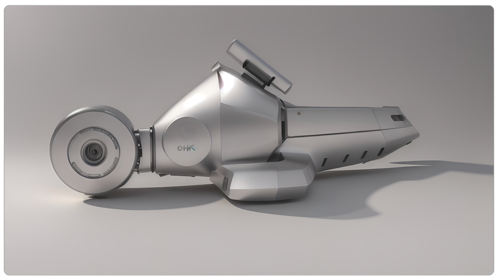
Figure 6
CFM Tweaks
Oftentimes, multiple rendering iterations can lead to some undesirable elements (Figure 7A) – eg. the lens in the middle of the LIDAR sensor, the screw holes on the body, or cut-out on the tail.
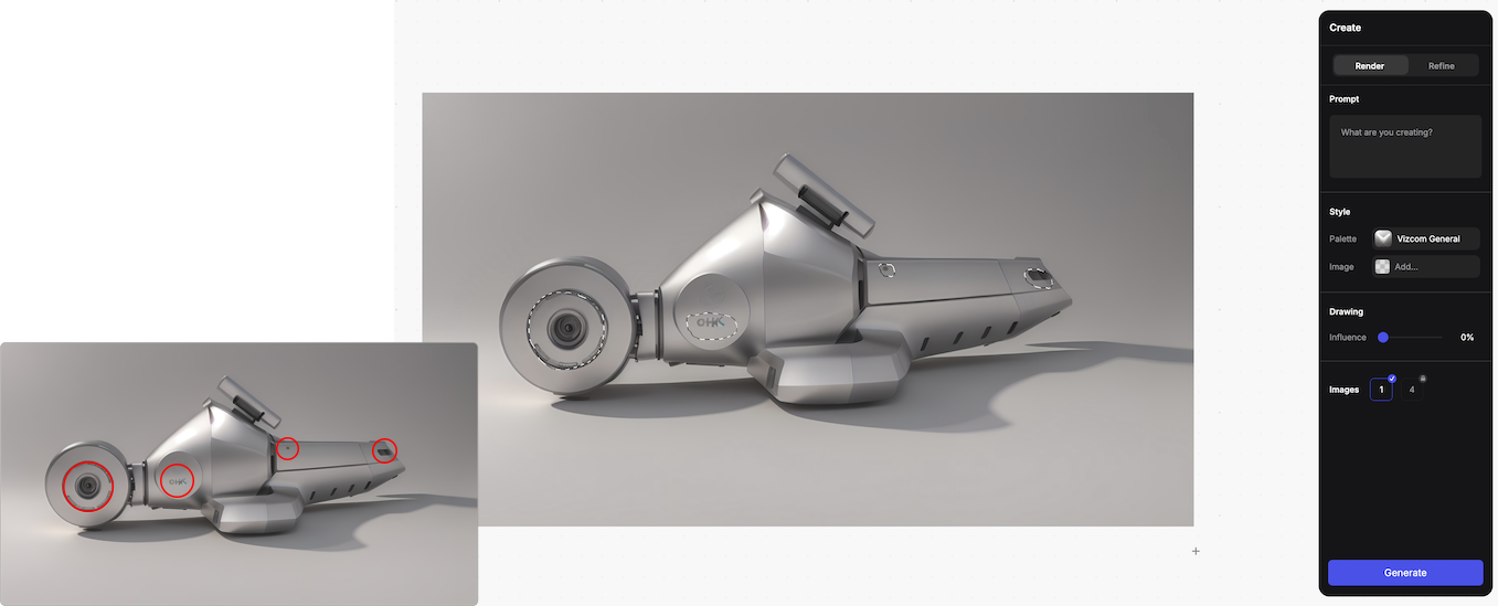
Figure 7A: selecting areas to remove unwanted elements
There is a simple way to remove these unwanted elements:
- Use inpainting tool (lasso/brush) and select the unwanted areas
- Leave the prompt section as blank
- Use 0% drawing influence
On hitting the generate button, all the unwanted elements disappear (Figure 7B)
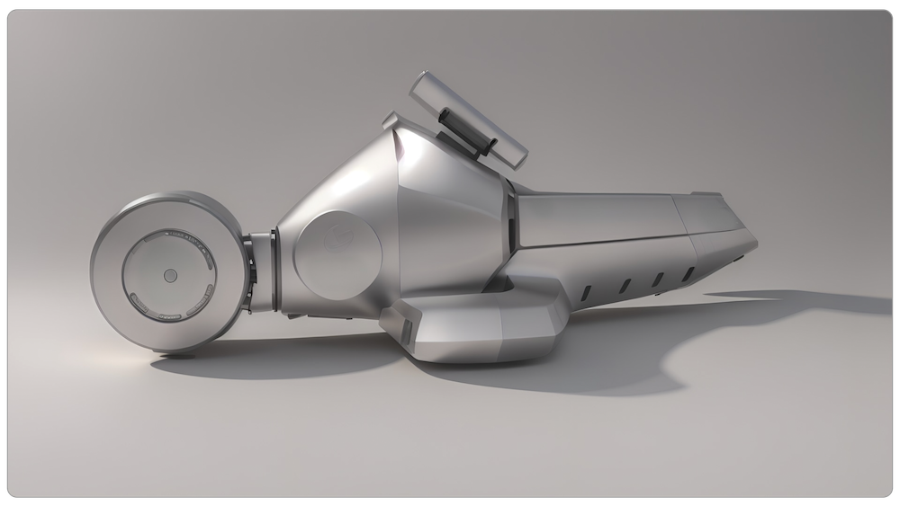
Figure 7B: unwanted elements have been removed
5. The Final Compilation
The different renders (the aluminum, matte black finish and LIDAR sensor) can be photo edited to create a polished version (Figure 8).
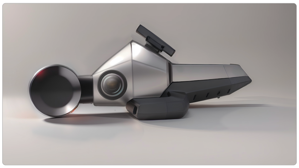
Figure 8
Finally, repeating all of the above tutorial steps with the other concept sketches quickly generated some compelling additional renders.
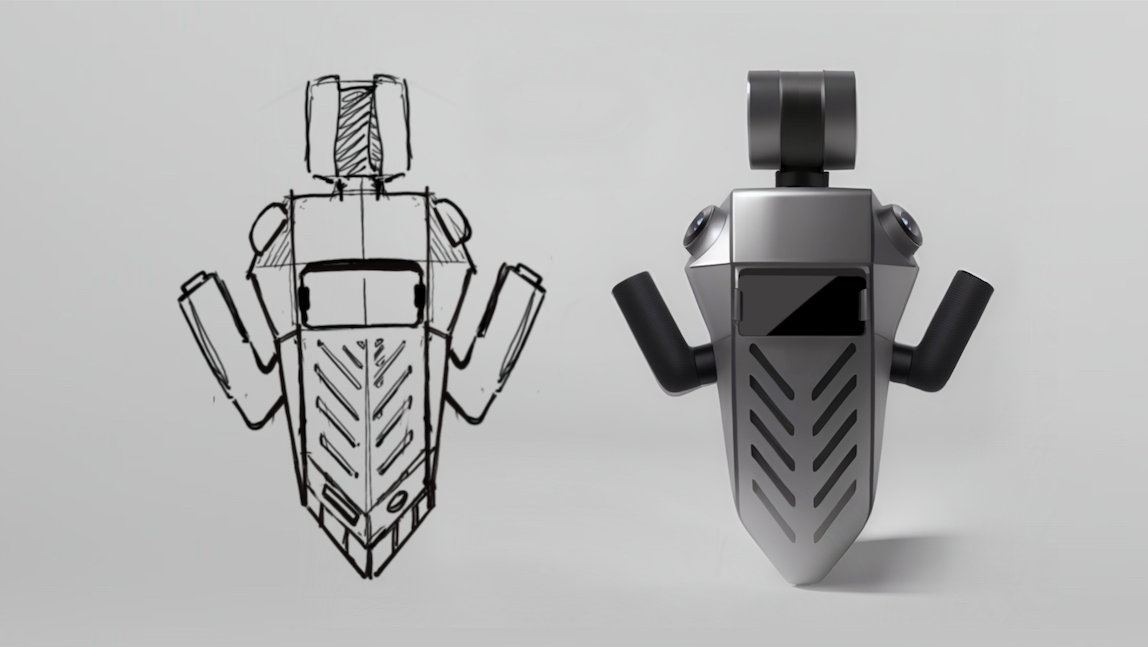
Figure 9
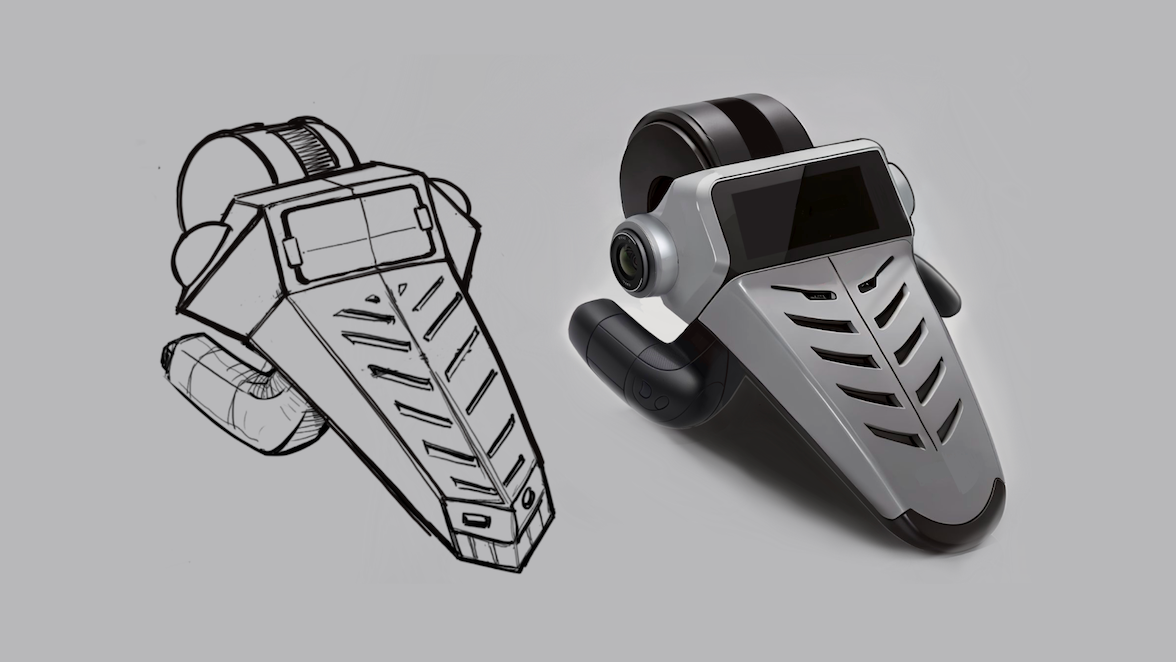
Figure 10
Conclusion
When MistyWest designed the real-life LiDAR-scanning device for our client, the timeline from initial ideation to the final 3D product renders was 4 weeks. Based on this exploratory exercise, had we used software such as Vizcom when we were in the conceptual design phase of the project, we could have reduced the timeline to final delivery by 50% – no small feat!
Besides enhancing the creative process and providing industrial designers with powerful new ways to visualize and refine their concepts, the integration of AI tools can help reduce time-to-market for products intended for commercial release, offering a significant advantage to our clients. As the design industry continues to evolve, the adoption of AI technologies will undoubtedly play a crucial role in shaping the future of industrial design, driving innovation, and pushing the boundaries of what is possible.
